A radio repeater is a combination of a radio receiver and a radio transmitter that receives a weak or low-level signal and retransmits it at a higher level or higher power, so that the signal can cover longer distances without degradation. In dispatching, amateur radio, and emergency services communications, repeaters are used extensively to relay radio signals across a wider area. With most emergency (and some other) dispatching systems, the repeater is synonymous with the base station, which performs both functions. This includes police, fire brigade, ambulance, taxicab, tow truck, and other services. The UHF CB service in Australia also use repeaters in much the same fashion as amateur radio operators do.
Full duplex operation
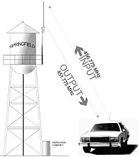
A repeater is an automatic radio-relay station, usually located on a mountain top, tall building, or radio tower. It allows communication between two or more bases, mobile or portable stations that are unable to communicate directly with each other due to distance or obstructions between them. The repeater receives on one radio frequency (the "input" frequency), demodulates the signal, and simultaneously re-transmits the information on its "output" frequency. All stations using the repeater transmit on the repeater's input frequency and receive on its output frequency. Since the repeater is usually located at an elevation higher than the other radios using it, their range is greatly extended. Because the transmitter and receiver are on at the same time, isolation must exist to keep the repeater's own transmitter from degrading the repeater receiver. If the repeater transmitter and receiver are not isolated well, the repeater's own transmitter desensitizes the repeater receiver. The problem is similar to being at a rock concert and not being able to hear the weak signal of a conversation over the much stronger signal of the band. In general, isolating the receiver from the transmitter is made easier by maximizing, as much as possible, the separation between input and output frequencies.
Frequency separation: input to output
There is no set rule about spacing of input and output frequencies for all radio repeaters. Any spacing where the designer can get sufficient isolation between receiver and transmitter will work. The narrowest documented spacing found in preparing this article is a system dismantled in the 1980s. One channel used on the Riverside County, California Sheriff's Department system, which was replaced by an 800 MHz trunked system, used 158.760 MHz as input and 159.090 MHz as output, a spacing of 330 kHz. The station callsign was KMH971. It is unusual to see systems with input and output spaced this closely. It is believed working systems have been spaced as close as 175 kHz. There is currently a narrow spacing in use in Alamogordo, NM used for the city EMS dispatching. Input is 155.715 MHz and output is 155.385 MHz which is also a spacing of 330 kHz. In some countries, under some radio services, there are agreed-on conventions or separations that are required by the system license. In the case of input and output frequencies in the United States, for example:
Amateur repeaters in the 144-148 MHz band usually use a 600 kHz (0.6 MHz) separation.
Systems in the 450-470 MHz band use a 5 MHz separation with the input on the higher frequency. Example: input is 456.900 MHz; output is 451.900 MHz.
Amateur repeaters in the 420-450 MHz band use a 5 MHz separation with the input being either on the higher or lower portion of the 440-450 segment of the band (the standard changes regionally). Example: output is 444.400 MHz; input is 449.400 MHz.
Systems in the 806-869 MHz band use a 45 MHz separation with the input on the lower frequency. Example: input is 810.1875 MHz; output is 855.1875 MHz.
Amateur repeaters in the 902-928 MHz band use a 25 MHz separation, with the inputs on the lower frequency.
Military systems are suggested to use no less than a 10MHz spacing.
These are just a few examples. There are many other separations or spacings between input and output frequencies in operational systems.
Same band frequencies
Same band repeaters operate with input and output frequencies in the same frequency band. For example,30-50 MHz is one band and 150-174 MHz is another. A repeater with an input of 33.980 MHz and an output of 46.140 MHz is a same band repeater. In same band repeaters, a central design problem is keeping the repeater's own transmitter from interfering with the receiver. Reducing the coupling between transmitter and input frequency receiver is called isolation.
Duplexer system
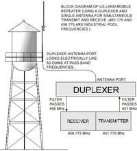
In same-band repeaters, isolation between transmitter and receiver can be created by using a single antenna and a device called a duplexer. The device is a tuned filter connected to the antenna. In this example, consider a type of device called a band-pass duplexer. It allows, or passes, a band, (or a narrow range,) of frequencies. There are two legs to the duplexer filter, one is tuned to pass the input frequency, the other is tuned to pass the output frequency. Both legs of the filter are coupled to the antenna. The repeater receiver is connected to the input leg while the transmitter is connected to the output leg. If the right specifications are chosen, the duplexer has a narrow-enough filter to prevent the repeater's receiver from being overloaded by its own transmitter. By virtue of the transmitter and receiver being on different frequencies, they can operate at the same time on a single antenna. Any anomaly or fault with the antenna or antenna feed cable will reflect transmitter power back into the receiver, possibly causing the receiver to be overloaded. The reflected power will quickly exceed the duplexer's filtering ability.
Combining system
There is often not enough tower space to accommodate a separate antenna for each repeater at crowded equipment sites. In same-band repeaters at engineered, shared equipment sites, repeaters can be connected to shared antenna systems. These are common in trunked systems, where up to 29 repeaters for a single trunked system may be located at the same site. (Some architectures such as iDEN sites may have more than 29 repeaters.) In a shared system, a receive antenna is usually located at the top of the antenna tower. Putting the receive antenna at the top helps to capture weaker received signals than if the receive antenna were lower of the two. By splitting the received signal from the antenna, many receivers can work satisfactorily from a single antenna. Devices called receiver multicouplers split the signal from the antenna into many receiver connections. The multicoupler amplifies the signals reaching the antenna, then feeds them to several receivers, attempting to make up for losses in the power dividers (or splitters). These operate similarly to a cable TV splitter but must be built to higher quality standards so they work in environments where strong interfering signals are present. On the transmitter side, a second transmit antenna is installed somewhere below the receive antenna. There is an electrical relationship defined by the distance between transmit and receive antennas. A desirable null exists if the transmit antenna is located exactly below the receive antenna beyond a minimum distance. Almost the same isolation as a low-grade duplexer (about -60 decibels) can be accomplished by installing the transmit antenna below, and along the centerline of, the receive antenna. Several transmitters can be connected to the same antenna using filters called combiners. Transmitters usually have directional devices installed along with the filters that block any reflected power in the event the antenna malfunctions. The antenna must have a power rating that will handle the sum of energy of all connected transmitters at the same time. Transmitter combining systems are lossy. As a rule of thumb, each leg of the combiner has a 50% (3 decibel) power loss. If two transmitters are connected to a single antenna through a combiner, half of their power will reach the combiner output. (This assumes everything is working properly.) If four transmitters are coupled to one antenna, a quarter of each transmitter's power will reach the output of the combining circuit. Part of this loss can be made up with increased antenna gain. Fifty watts of transmitter power to the antenna will make a received signal strength at a distant mobile radio that is almost identical to 100 watts. In trunked systems with many channels, a site design may include several transmit antennas to reduce combining network losses. For example, a six-channel trunked system may have two transmit antennas with three transmitters connected to each of the two transmit antennas. Because small variations affect every antenna, each antenna will have a slightly different directional pattern. Each antenna will interact with the tower and other nearby antennas differently. If one were to measure received signal levels, this would cause a variation among channels on a single trunked system. Variations in signal strength among channels on one trunked system can also be caused by:
failed parts in the combiner
characteristics of the design
loose connectors
bad cables
mistuned filters, or
incorrectly installed components.